by Penny Reiswig
In the early stages of one's pipemaking career, every new project seems to beget a new tool, or jig, or method of working, as one discovers new obstacles that need overcoming. Sometimes the solutions are easy to find, other times it takes more ingenuity to design a solution that will fulfill our specific needs. For me, this kind of problem-solving is one of the most rewarding parts of instrument making. It's a kind of meta-creativity: building the tools that will help build the instruments that will make music, that will hopefully make the world a better place.
Plus, as a wise man once said, "you can never have too many tools." Sometimes the tools we invent along the way have a single convenient purpose, and sometimes they end up being so useful for so many tasks that they become really indispensable - something we can't imagine living without.
Most of what I know firsthand about wood machining and bagpipe making comes from Rob Moore of Cobble Hill, BC, Canada, who makes instruments with a sense of precision acquired during his career as a machinist. My own approach to pipemaking has naturally evolved in the same direction. Though I don't have anything like Rob's machining experience or collection of tools, I'm improving both, "bit by bit."
In the spring of 2004, I set out to build a set of Northumbrian small pipes, which would present a number of new challenges, mostly related to the intricate keywork of the chanter. I had done a small amount of keywork up to that point, so the keys themselves would present little difficulty. It was the thought of 10 key mounts, keyway slots, pivot holes, toneholes and pad seats, all at different angles around the very narrow chanter, that had me worried. I had examined several chanters (whose makers shall remain nameless) where the keyways weren't exactly in line or square with the toneholes or the pivot holes, so the keys had needed to be bent or otherwise contorted to operate freely.
I knew a better system would be required, one that would satisfy my own need for accuracy and repeatability. I had seen Rob do these jobs with his milling machine equipped with a rotary dividing head, but I didn't (and still don't) have the space or the money for such a setup, nice though it might be. After puzzling over my options, it became clear that I would need to build my own system for doing the keyway machining. The metal lathe is already an excellent workholding device for bagpipe parts, so I decided to do these operations using the lathe rather than build some workholding/positioning system onto, for instance, a drill press.
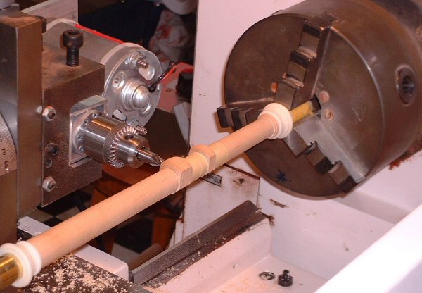
My system is in two main parts: first, an indexing plate, allowing the lathe spindle to be locked in, and later returned to, any of several positions around its rotation. The other component is a small milling/drilling machine held on the lathe carriage, which can be presented to the work, and moved accurately in 3 dimensions.
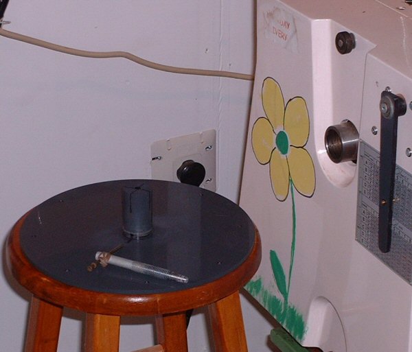
The indexing plate is little more than a disk attached to the lathe spindle, with holes in it to receive a locating pin which locks the disk (and thus the spindle) in place. The larger the disk, the more accurate the hole placement can be, so I made my disk the maximum size my lathe can swing, about 12". It's made of 1/4" PVC plastic. Attached to one side of the disk is a piece of PVC rod which is a smooth fit into the outboard end of the lathe spindle hole. This rod is turned into a kind of expanding collet, by slotting the end, and drilling the inside to receive a bolt with a tapered point.
So when the rod is inserted into the spindle hole, tightening the bolt expands the end of the rod, securing the disk onto the spindle. I laid out and drilled eight 1/4" holes near the edge of the disk, which gives 45-degree increments for operations around a chanter or regulator. More holes could be added later, but so far I've found eight positions to be adequate for my needs. The locating pin is a piece of 1/4" brass rod, secured at the end of a pivoting arm attached to the lathe headstock housing. When assembled, the whole thing looks kind of like a record player attached to the end of the lathe. With the lathe drive motor disengaged, the centre bolt is tightened so the disk is securely locked into the spindle. The locating pin is then engaged into whichever hole is needed, to present any one of eight "faces" of a workpiece to the cutting tool. As long as the workpiece and the disk remain locked onto the spindle, they can return to any position as needed. It's satisfyingly stable and repeatable.

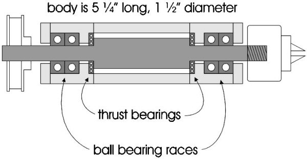
The milling/drilling spindle attachment was more ambitious. Again, after examining several commercial options, I decided to make my own. For some reason I figured that my machining expertise was up to the task, and set about designing the thing. The spindle itself was turned from 3/4" tool steel, and the body components from 1.5" aluminum rod and tube. Every part is round, and therefore fairly straightforward to machine on the lathe. Each end of the spindle has two ball bearing races to handle side loads, as well as a thrust bearing. Once assembled, the spindle housing fits inside a section of 2" square aluminum tube, which is convenient to clamp in the vertical slide of my lathe. The front of the spindle is threaded for the installation of a 3/8" Jacobs chuck, and the rear has a drive pulley attached. The motor is 1/4 horsepower, 90 volts DC, purchased online from a surplus dealer. Its speed is controlled by an electronic SCR motor controller, also surplus, found on eBay for about $10. I chose the pulley sizes to give the spindle a maximum speed of about 2000 RPM.

Although it's certainly not perfect, my home-built milling/drilling spindle has been good and reliable. It has several advantages for me over other solutions I had investigated. Most importantly, the 3/8" Jacobs chuck allows me to use ordinary drills or (more usually) endmills for drilling holes up to 3/8" or larger, which would have been more difficult with some of the smaller collet-based rotary tools.
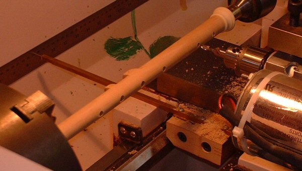
In use, the square body of the milling spindle is held in the vertical slide of the lathe. Thus it can be moved up/down with the vertical slide, left/right with the lathe carriage, and in/out on the cross-slide. With the vertical slide set at centre height, drilling toneholes is easily done, always in perfect alignment. The front, back, and sides of the pipe are precisely (and repeatably) located with the indexing plate.
Keypad seats can be formed with a flat endmill, or a specially reground bit could be used to produce the "volcano" shaped seats.
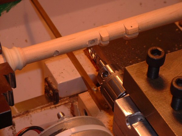
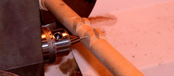
Keyways are usually cut with a 1/8" endmill, exactly aligned with their corresponding toneholes.
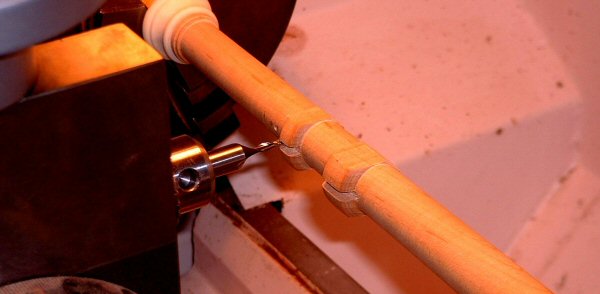
The milling spindle is also a handy tool for removing the bulk of waste material from the key mounts.
Once a keyway is milled, the pipe is rotated through 90 degrees, and the spindle again locked in place by the indexer, so the key pivot hole can be drilled exactly square to the keyway.
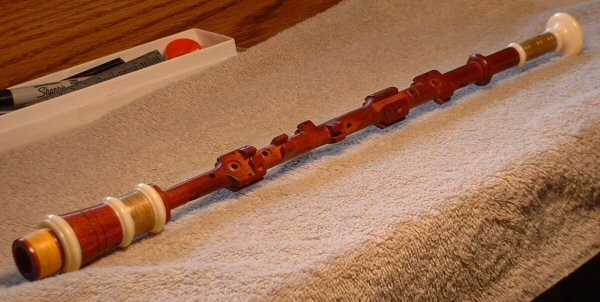
It took a while before I was ready to unleash the new drilling machine on my first Northumbrian chanter. In fact, though, all the drilling and milling operations went smoothly and according to plan, and the 10-key chanter fit together beautifully. This little machine instantly became the most useful tool in my shop (other than the lathe itself, of course) and is constantly finding new uses. It's one of those tools that makes one ask "how did I ever get along without it?" (And also "who needs a milling machine when you've got one of these?")
I hope this hasn't been too boring. Every pipemaker, professional and hobbyist alike, must have some tool that does this same job, and I'd certainly be interested in learning about yours, or sharing more info about mine. Questions, comments, tips, and suggestions would all be weclome. I can be reached by email at pennyreiswig@gmail.com.
.