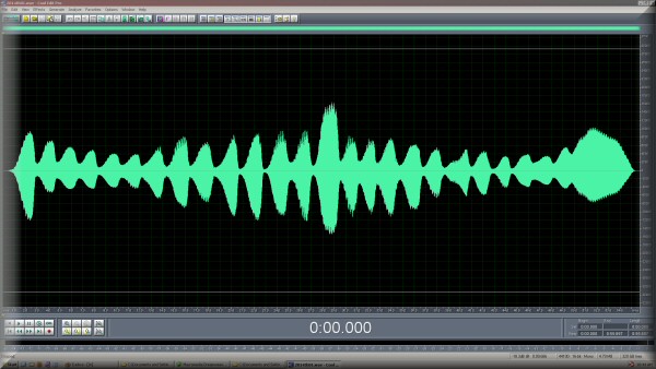
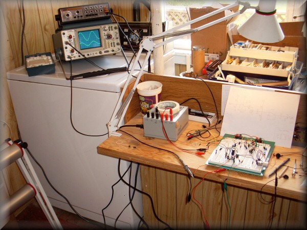
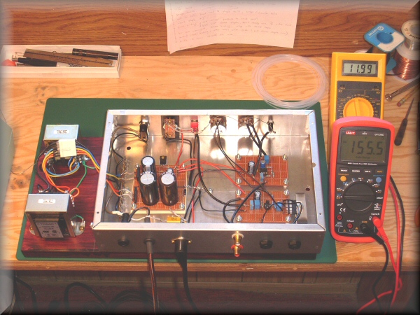
Designing and testing the amplifier cicuitry. The power amp and pitch preview amp are both built up on breadboard, and i'm feeding them with a function generator. The oscilloscope lets me examine what's happening to the signal as it goes through each amp. This way i can make sure the signal levels are correct, there's no distortion or other problems, so everything will be ready for the actual instrument. Of course, i'll build the final versions on proper circuit boards once i'm done tweaking them.
Here we have one of the most important parts - the pilot light. (Well, not really all that important, but i like them to look nice, and i have a weakness for these pretty jeweled lamps.) On previous instruments, i've had a separate pilot light in addition to a red/green LED for a mute/play indicator. That's redundant though: since the mute/play light is always lit anyway (either red or green), it could just as well serve as the main power light. So this time, i'm combining those two functions into one lamp. I've got a super-bright red/green LED behind a clear jewel lens. Because these lamps normally use miniature incandescent bulbs, i had to replace the bulb holder with a totally custom assembly. The piece of black plastic is not a mock-up of a front panel; rather it's got a piece of perfboard screwed onto it from behind, which is holding the LED in the centre of the lens. The plastic part and everything behind it will go inside the chassis, behind the final front control panel.
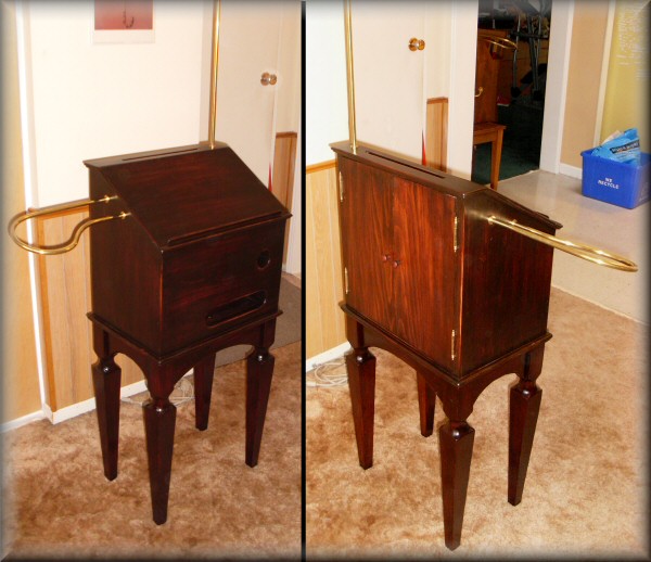
(16 May) Here is the final cabinet, beautifully made by Peter at Natural Edges Woodworking. It's not your grandfather's RCA, that's for sure! It's a little more interesting, with the turned sections in the legs, and the beaded trim at the top & bottom. It looks like it would be at home in a church or concert hall. The cabinet also lifts off the legs for easy transport.
Next, i have to make the innards to be worthy of this cabinet!
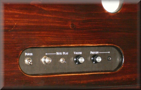
(1 June) The lower chassis is finished. The power transformers are outside the box on the left; they connect with the white 6-wire connector so i can remove the chassis for servicing. Inside the chassis are only three small circuit modules. At the left is the power supply, which gives +12v for the tube filaments and the amplifiers, and zener-regulated +150v for the upper chassis tube circuitry. On the right side are the pitch preview headphone amplifier and the main audio power amplifier. The power amp uses my new favourite amplifier IC, the 4-watt Panasonic AN7523N (unfortunately obsolete). The near side of the chassis has the power cables as well as the jacks for signal inputs & outputs. The far side is the main control panel: power switch, lamp, mute switch, and the volume controls & headphone jack.
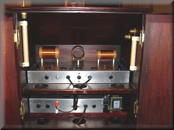
(16 June) The inside of the cabinet. The lower chassis is in place & ready to go, while the upper chassis is still empty except for the oscillator coils.
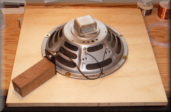
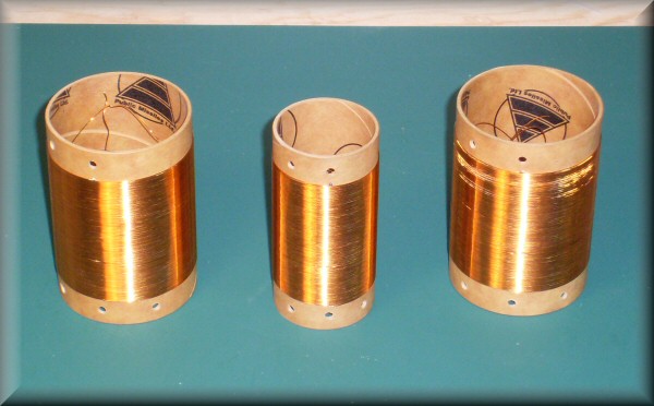
On the left & right sides, you can see the small paper covered tubes connected to the antennas. They contain the small coils which take the place of the large antenna coils i made the last time around. They have the same inductance, and should give the same performance, while being a fraction of the size.
The holes through the shelf and out the bottom are for running cables in & out and between the chassis, and also for ventilation.
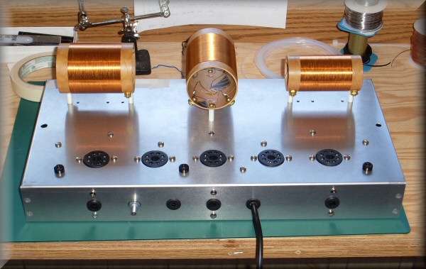
The upper chassis has all the hardware installed, and it's ready for the electronics. Three of the holes out the back are for adjusting the trimmer capacitors to fine-tune the oscillators. Last time, i had the adjustment holes on the top, which was fine in the open cabinet, but since this cabinet opens from the back, that's where i need the adjustment access.
The other two holes are for cabling: this time i'm using separate cables to connect power and audio between the two chassis.
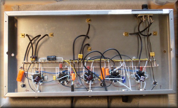
(23 June) And here's the completed upper chassis. I work pretty slowly (or, let's say deliberately) at this kind of construction, so it took basically all weekend to do this wiring.
The first tests were successful - none of the magic smoke escaped, and it was tuned close enough to make some sounds. So far, so good!
Next is to spend a little time fine tuning and adjusting. It's getting really close now.