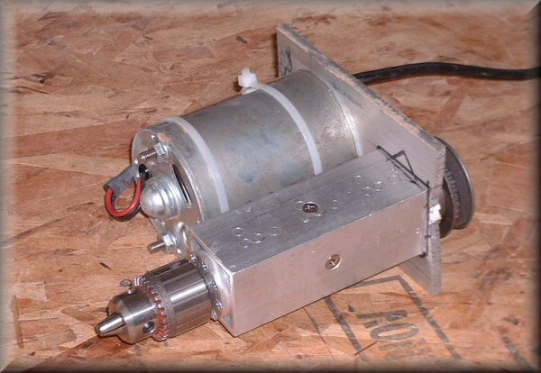
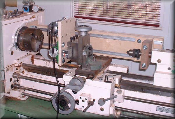
This is my "mark 1" machine, made in 2004. I'd never built anything like this before, so i kind of over-designed it, but it works fine and did all the machining for the Northumbrian chanter fingerholes, key mounts, key slots, pivot holes, and pad seats. It's made all the fingerholes on all my pipe chanters since then. The construction and use of this machine was documented for a 2006 article in The Pipers' Review, a journal for uilleann pipers and piping.
At the time, one of the main features i wanted was a Jacobs-style drill chuck out front, so that it could hold any size twist drills, as well as milling cutters. As it turns out, this was the weakest point of the design. Having the chuck threaded onto the end of the spindle introduced considerable runout/inaccuracy, as well as sacrificing the rigidity needed to mill slots in metal.
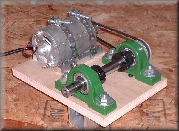
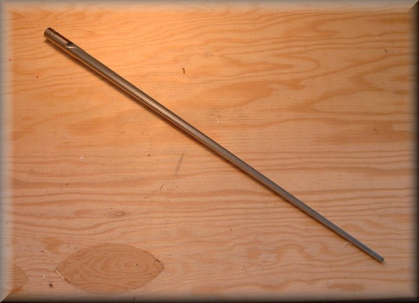
Here is the "mark 2" machine, made in 2008. It's far less sophisticated than its predecessor, but is better in almost every way. The spindle is made from a piece of 3/4" drill rod. I drilled and reamed a precision 3/8" hole in the nose, to accept a standard 3/8" shank endmill, which is secured in place with an Allen key set screw. This arrangement will be stronger and more accurate than the drill chuck, especially for working in metal. I've actually been using endmills exclusively for drilling fingerholes anyway, so i'm not really giving up much versatility by not using a chuck. For the 1/16" key pivot holes, i'll embed a 1/16" twist drill in a 3/8" steel shank and hold it the same way as an endmill.
The spindle itself is supported in two 3/4" pillow block bearings, along with clamping collars. It sure doesn't look as slick as mark 1, but it's way more robust and accurate, which is really all that counts. Also, it'll be much easier to take apart & maintain if and when necessary.
The motor is the same one, stolen from the first version. It's 90VDC, 1/4 HP, run from a surplus variable speed SCR controller. The pulleys are sized to give a maximum spindle speed of about 2000 RPM.
These are the first two test pieces from machine mark 2. The 1/8" slot in a piece of hardwood is much closer to nominal size than with the mark 1 machine. This will make for better fitting keyways, with less wobble. The new machine also had no problems at all chewing through the steel rod.
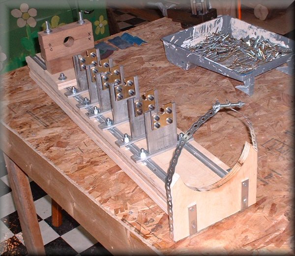
For machining long skinny conical reamers, though, i'll need some support along the length, in order to keep the workpiece from deflecting and vibrating...
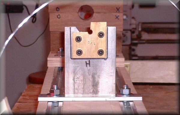
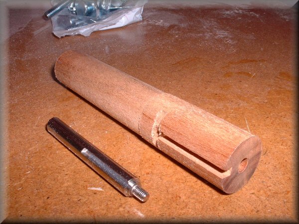
Here's the first of the individual reamer support struts. It rides in the T-slots, so it can be positioned anywhere along the length of the workpiece. More specifically, it will be placed where the partial hole (in this case 1/4") snugs up to the diameter of the tapered workpiece. So there will be a set of these in 1/16" graduated sizes, which will support whatever reamer i want to work on. The brass insert plates are removable in case i need to make more, for instance in order to work in a different range of sizes.
The hole will be opened up to allow minimal clearance to machine away exactly a quarter section of the workpiece, while still gripping it around (almost) the other 3/4.
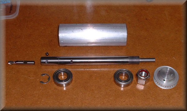
Ok, an interlude while i build machine mark 3! I stumbled across this spindle design, and it was so simple and elegant that i couldn't not build one. This has all the good features of my mark 2 machine, while being even stronger and more compact. (Plus it looks way cooler - like it was built by someone who knows something about machining! Mark 2 kind of looks like it was built by kids in the backyard.) Many thanks to Dave at www.buildyouridea.com.
My spindle is made of 3/4" drill rod, and holds 3/8" shank endmills. It's supported by 2 ball bearings, snugged in between an e-clip at the front, and a locking nut at the rear. The whole thing goes in a 2" aluminum tube.
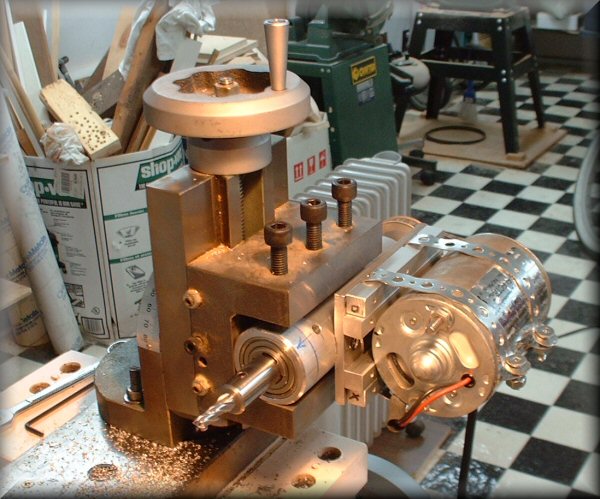
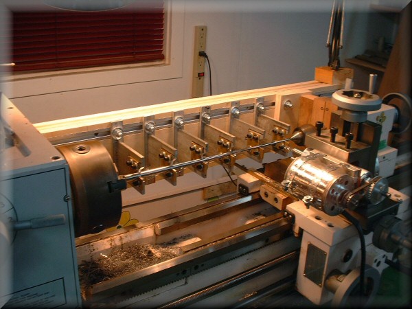
Here i've got a conical reamer blank turned down and mounted in the supports. Everything is tightened down and feels really good and rigid.
I've been sketching and mentally designing this setup for a couple of years now, and it's pretty exciting to finally see it in real life. It'll be even more exciting if it all works as planned...
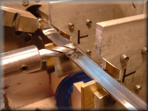
Here we are at almost full depth. I'm using a 5/16" endmill, taking .005" cuts, which means 55 or so passes to reach halfway through this reamer.
The whole setup is working really well. Machine mark 3 is humming along smoothly, and the support structure is keeping the reamer beautifully steady.
I cannot say how satisfying this is to use. As i said, this has been years in the making, and is the last major hurdle in terms of toolmaking i need for bagpipe making. This also is the only process for which i would have needed a milling machine, and my little machine mark 3 never broke a sweat during the ~3 hours of milling on this steel rod.