This time, i decided to go for a complete scratch build, based on a schematic presented in a 1996 DIY article by Robert Moog. This schematic is what would later become the Moog Etherwave theremin, so i was pretty sure it would have better playability than the "Theremax" kit i built a few years ago. One of the challenges about NOT working with a kit is sourcing all the parts. In fact, two absolutely key parts are no longer manufactured, but another theremin hobbyist online pointed me to a ham radio supplier in the UK that still carries them "while stocks last." I did have some "plan B" parts figured out, but it's nice to work with the originally specified components if you can. The other big challenge in this build was the circuit board layout & design process. It was easily the hardest part of this project (maybe one of the harder things i've ever done), but was fun and interesting nonetheless. I feel like i've learned an awful lot about electronics in general, and theremins in particular.
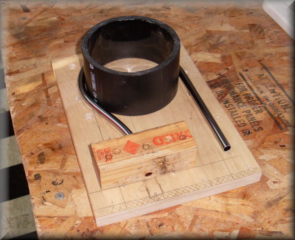 |
While i'm planning the electronics, i can work on the physical stuff, starting with bending the volume antenna. This is 3/8" chrome-plated copper water supply tubing, which is pretty soft and easy to bend. Both antennas then get filled with epoxy to make them stiffer and more resistant to bending/denting.
|
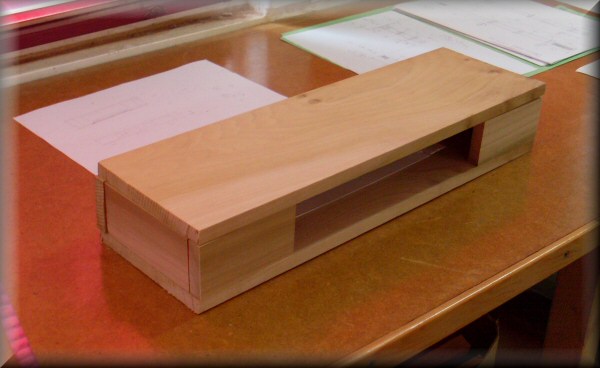 |
The cabinet pieces are rough cut from poplar. The box is 18" long, 5.5" deep, and about 3" tall. I'm trying to follow the Etherwave dimensions as much as possible. I'm also planning to attach the panels together with glue and dowels instead of screws. I want to try and minimize the amount of metal in the cabinet, which could affect the control zones of the instrument.
|
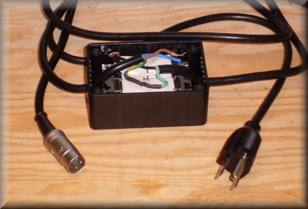 |
The power adapter is nothing but a transformer in a box. The theremin needs a good (earth) ground to work properly, which means you need the third prong of the power plug. Normal AC/DC adapters typically only have 2 prongs. So i've carried the ground wire straight through to the middle pin of the DIN-3 connector, and the other two pins carry 15VAC. The rectifying and filtering is done inside the instrument, and ends up as +12 and -12 VDC. |
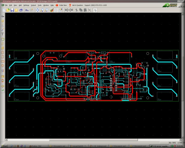 |
This is the software i'm using to design the circuit board. It's called "PCB Artist," and comes from www.barebonespcb.com, which is the cheapest PCB protoyping service i've found so far. You start by drawing the schematic, then convert it to a blank circuit board, and then the real work is in laying out the components and routing all the connections. The software checks to see that your circuitry matches the original schematic. This is my first time doing this kind of design, and while it's very clear i'm no electrical engineer, i'm pretty happy with the layout. |
|
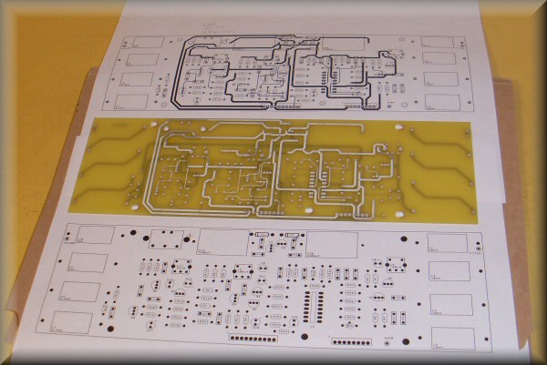
So you press "order" in the software, and a couple of days later a shiny new PCB arrives on your doorstep. This is the "barebones" process, so it's just tin plated copper on both sides - there's no green solder mask or silkscreen printing. The only map i have of where stuff goes is the layout print from the design program. |
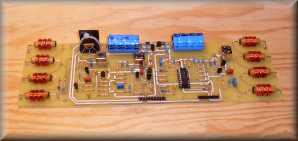 |
Here's the finished circuit board. It's got 102 components that needed to be soldered in. Without a top silkscreen, it's easy to make mistakes and put a component in the wrong place. I did made (only) one such mistake, which was easy to spot because later on, the hole i needed for another component was already occupied! Fortunately it's pretty easy to desolder and move stuff around. |
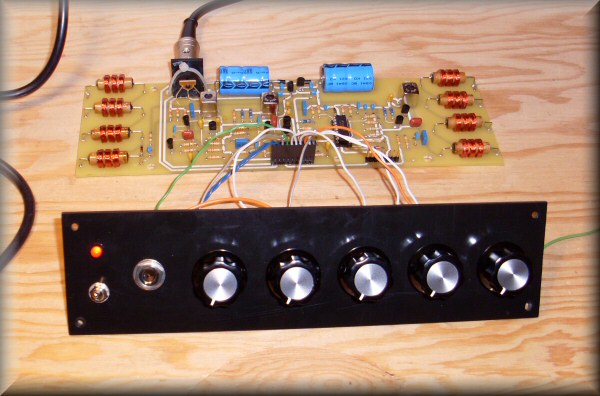 |
I've hooked up the front panel, and connected the power supply for the "smoke test." So far so good. Of course, at this point, there's no antennas or speakers, so the only indication that it's working at all is the red LED silently glowing like HAL 9000. (Well, that, and the lack of smoke.) |
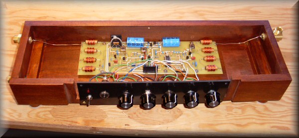 |
Here's the PCB in its new home. The cabinet is assembled, stained, and varnished. The antennas will connect to the 3/8" tube compression fittings which are attached to the ends.You can see the front panel is a little too short for the space - that was the biggest piece of plastic i had handy. Eventually i plan to add a few more features, so i made the space long enough to accomodate a longer panel with one more knob and jack. |
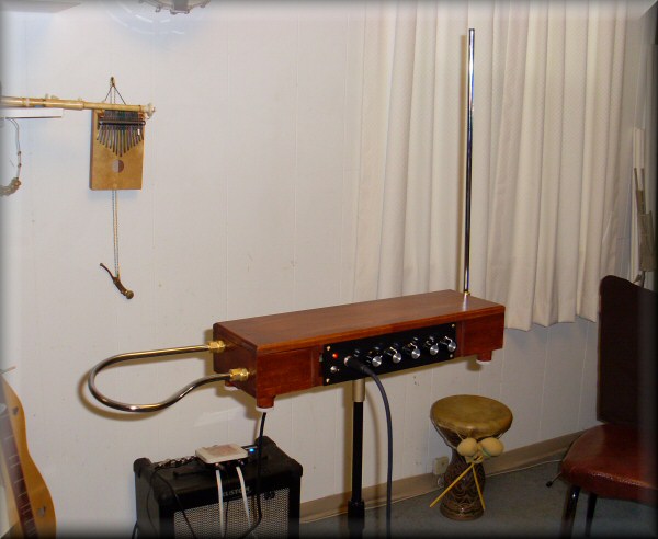 |
Complete! It sits on a mic stand (with an improvised flange made of plumbing parts) or on feet. A theremin takes a fair amount of tuning and tweaking before it sounds at all, but the instructions in the article were excellent, and pretty soon it was playing nicely! This thing has a lot of sounds in it. The rightmost two knobs control the wave shape and harmonic content, so it can sound anywhere from creamy and smooth to buzzy and harsh.
The pitch range is less than the Theremax, which means that the notes themselves are bigger and therefore easier to find. Also, the pitch field is more linear, which means that the notes are somewhat more evenly spaced through more of the range. (Again, making it easier to play, especially the higher notes.) In fact, this instrument is night-and-day easier to play than the Theremax. There are apparently still better and more linear theremins out there, but i can't imagine myself needing anything better than this. (Never say never, though! I can see myself one day getting the bug to build an all-tube theremin - or two - or three...)
Thanks to Dr. Moog for an excellent article and great sounding, robust design. Also to the folks at the ThereminWorld forums, for their collective encyclopedic knowledge of theremin electronics.
|