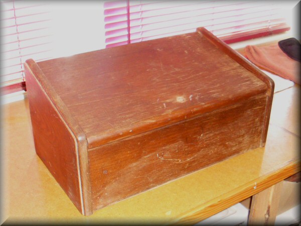
How big is a theremin? Well, this one will be exactly the size of a breadbox. Just like my first theremin kit, i got a neat old breadbox from eBay, which will make a nice cabinet. This one has the lid opening upwards, which will be great for accessing the tubes. I'm planning to sand the box down and refinish it, but it's in great structural condition.
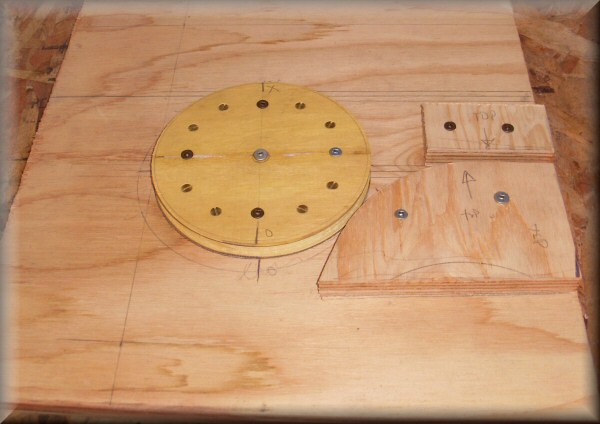
Here's my new and improved jig for bending volume antennas. The round part is a wooden wheel i made but never finished during the early stages of my hurdy-gurdy project, and it was just about the perfect size for the volume antenna. The moral of the story is: never throw anything away!
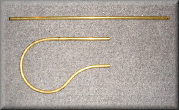
The antennas, after annealing and bending the volume loop. I wanted to use regular 3/8" brass tube instead of the chromed copper water supply tube i used last time around. I'm used to bending this kind of tube into much tighter curves, so this was no problem at all. I didn't even bother filling it to keep it from kinking.
The top of the pitch antenna has a small delrin cap, which makes it look nice and finished.
Art Harrison specified plate-style antennas in his original design, but i'm kind of a traditionalist, so i'm going with the more standard rod and loop. Others have apparently had success using the old-school antennas with this design, so i'm not too worried.
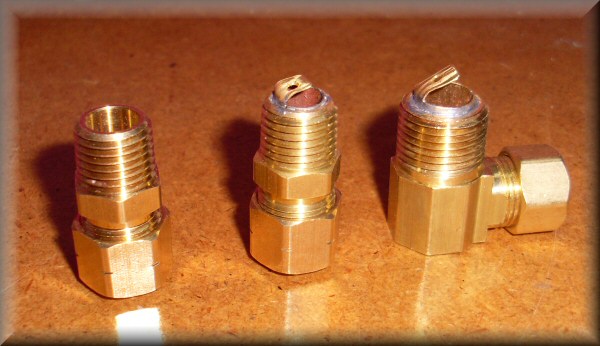
I'll be using these 3/8" tube compression fittings to attach the antennas: the straight ones for the volume loop, and the right-angle one for the pitch rod. I got this idea from the construction of the Moog EM/Etherwave theremin, and it works well. Especially on this breadbox, where the whole top is the lid, i have to attach the pitch rod to the side of the box., as opposed to straight up out the top.
Two of the fittings have solder lugs attached, so i can connect wires from the theremin circuitry. I did this by soldering some thin walled brass tube into the fittings, leaving the small tags hanging out.
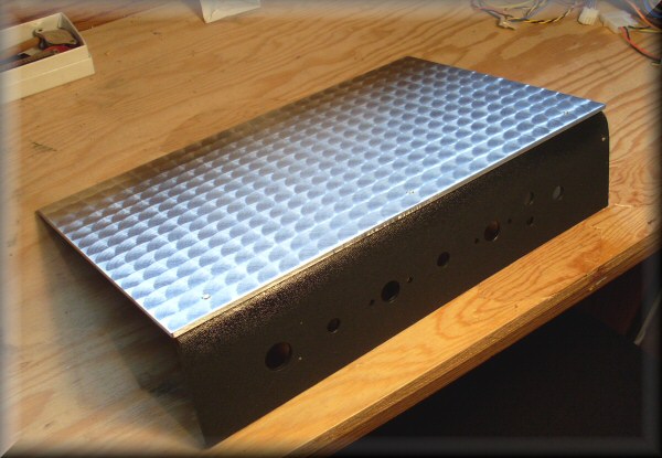
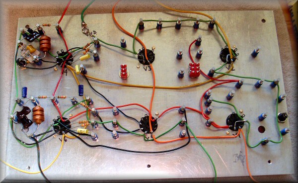
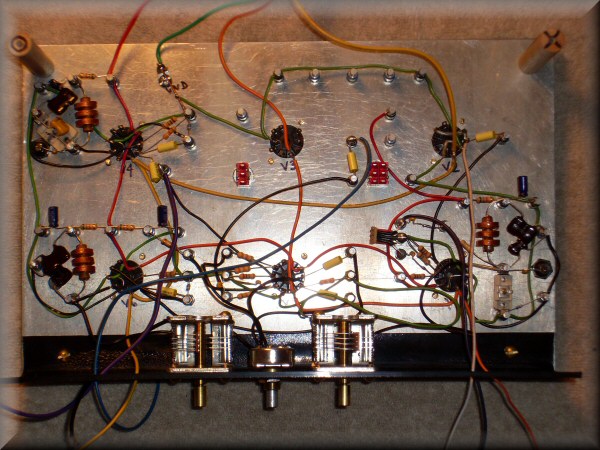
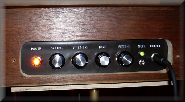
Here's the chassis and front panel assembly. The chassis plate is 1/8" thick aluminum; the large blank area was crying out to be engine turned. I'd never done it before, but this was the perfect time to try. It was actually quite straightforward - i used a "unitized scotchbrite" abrasive wheel in my drill press.
The control panel is a piece of thermoforming plastic, bent over and screwed up to the chassis.
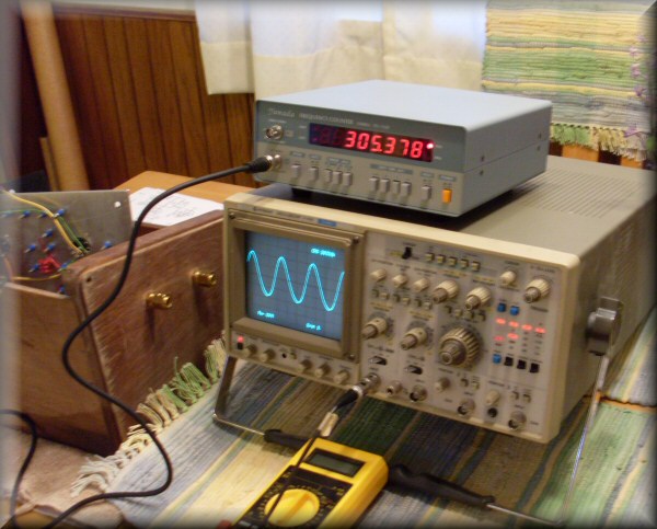
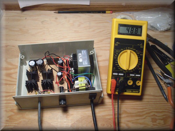
I've plugged in one tube to run the single oscillator, and it seems to work fine! A beautiful sine wave, and the frequency decreases as i approach the pitch antenna. Right now it's running at about 305 kHz, which is right in the ballpark of where it's supposed to be.
So far, so good!
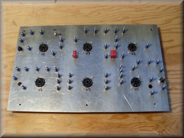
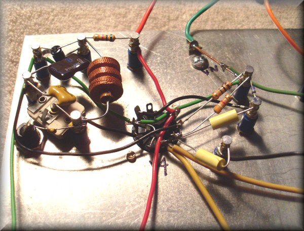
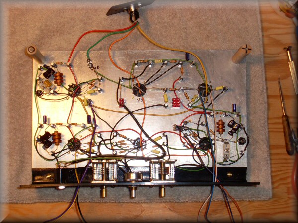
That's two sections down out of six. (I'm kind of working on each tube socket and associated cluster as a unit.) So i've got the variable and reference pitch oscillators made, and they're both working fine!
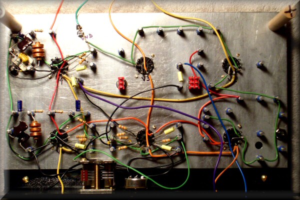
The rest of the wires running around are all for the ground (green), high voltage (red) and tube heaters (yellow/orange).
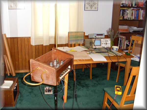
Here we are in my dining theremin testing room. The bunch of wires hanging out the front of the instrument are there so i can connect the scope/counter/multimeter to various key test points inside, to check that everything's working as planned.
...And it does work! There's some tweaking and fine-tuning to do, but it is playing and sounds quite nice. The tone control does give a lot of useful variation in timbre.
The instrument as designed by Art Harrison has the volume behaving "backwards" to the original theremins: as the player's hand gets closer to the antenna, the volume increases. That's his preference, but i'm used to the closer=quieter behaviour of my other theremins, so this one feels really unnatural to me.
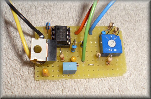
So i designed this little module to reverse the volume response. It goes after the volume circuitry, before it's fed into the amplifier tube, and flips the control voltage upside down. It uses an LM337 and a trimpot to generate a negative reference voltage based on the normal behaviour of the volume tubes, and an opamp (NE5532 which is what i had handy) as a differential amplifier to flip the control voltage relative to the reference. There's a switch to select the amount of gain given by the opamp, which also allows it to widen the dynamic range somewhat. Here's another reason to use +/-12vdc for the tube heaters: i can power this module!
The whole thing fits in a 35mm film canister tucked away inside the instrument; it's switched in or out of the circuit with a toggle switch on top of the chassis. It's kind of a shame to stick a solid-state kludge like this in the midst of an elegant tube theremin, but i'm not expert enough to do it with tubes.
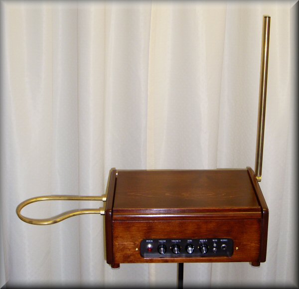
It's finished! I sanded down the breadbox, stained it and varnished it. And it looks great, though i do say so myself - like it was meant to be a theremin since the day it was made!
You might notice the pitch antenna has gotten thicker. I ended up replacing it with a 3/4" diameter tube. It more closely approximates the surface area of the originally-specified plate antenna. The skinnier tube didn't present as much capacitance to the instrument, so the available pitch range wasn't as large as i wanted. The new thicker antenna does give a greater pitch range.
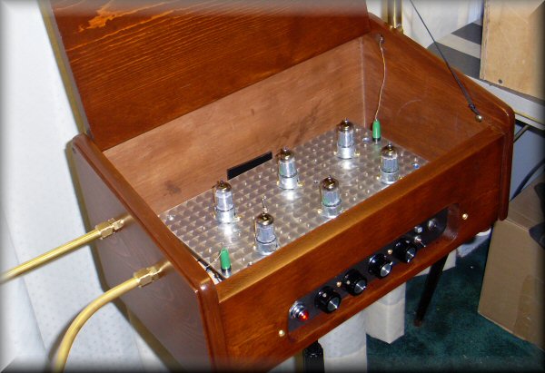
A picture with the lid opened to reveal the chassis and tubes. The antennas connect with banana plugs, so the guts of the instrument can be lifted right out of the cabinet.
(And no, i did not bother staining or finishing the inside...)
Click the notes for a sound sample. I am blown away by the loveliness of this instrument's voice. I was playing the EM theremin while the finish was drying on this cabinet, and it just sounds like a kid's toy to me now. I have seen the light, and it is the warm glow of a vacuum tube! (Uh, heard the light?)
Many many thanks to Art Harrison for a great project and instrument!
(Today also happens to be my sister's birthday. Happy birthday Jenny!!!)